Introduction
This blog shows how to implement Microsoft Hyper-V Failover Cluster over Fibre Channel (FC). All procedures outlined are conducted purely within a Lab testing environment.
Hyper-V is a Microsoft hardware virtualization solution that enables the creation and operation of virtual machines (VMs). Each VM functions as a standalone system capable of running its own operating system and applications, providing enhanced flexibility, cost savings, and efficient use of hardware resources.
Hyper-V operates each VM in its isolated environment, enabling multiple VMs to run concurrently on the same hardware. This setup prevents crashes impacting other workloads and allows different users, groups, or services to access individual systems.
A Hyper-V failover cluster is a set of independent Hyper-V servers (nodes) that work together to enhance the availability and scalability of clustered roles, using a centralized SAN iSCSI or FC storage. When a node fails, other nodes in the cluster take over, maintaining high availability.
Block Diagram
The following diagram shows the Hyper-V Failover Cluster over FC:
 Figure 1: Block Diagram
Hardware
The following lists the hardware used for testing:
|
Item
|
Qty.
|
Description
|
Version
|
|
Physical Server
|
8
|
Hitachi Advanced Server HA810; 2x Intel Xeon Silver 4110 (8C, 2.10Ghz); 256 GB RAM; 1 x SN1600Q 32Gb 2p FC HBA
|
Firmware Version: 2.96
|
|
25G NICs
|
2
|
Broadcom P225p NetXtreme-E Dual port 10Gb/25Gb Ethernet PCIe Adapter - NIC
|
Firmware Version: 223.1.96.0
|
|
25G NICs
|
2
|
HPE Eth 10/25Gb 2p 631FLR-SFP28 Adapter
|
Firmware Version:
226.1.107000
|
|
Physical
Storage
|
1
|
Hitachi VSP E990
|
SVOS Version:
DKCMAIN: 93-07-23-60/01
|
|
10/25G Switch
|
1
|
Cisco 93180YC-FX
|
BIOS: version 05.44
NXOS: version 9.3(5)
|
|
Virtual Machine
|
80
|
1x Virtual Processors; 8GB RAM
|
N/A
|
Software
The following lists the software used for testing:
|
Item
|
Machine
|
Description
|
Version
|
|
Operating System
|
Physical Server
|
Microsoft Windows Server
|
Version: 2022
|
|
Virtual Machine
|
RHEL
|
Version: 8.6
|
Configuration and Setup
The following lists the high-level workflow to implement Hyper-V Failover Cluster over FC:
1. Storage Layout.
2. Installing Hyper-V on Windows Server.
3. Configuring the Failover Cluster on Hyper-V.
4. Configuring NIC Teaming on Hyper-V.
5. Creating and configuring the vSwitch.
6. Creating and configuring VMs.
Storage Layout
● An 18TB DP volume is carved out of 4x Parity Groups on Hitachi Virtual Storage Platform E990 (VSP E990) storage system.
● The volume is mapped to all physical servers and shared among the Hyper-V cluster nodes.
● Additionally, 80 more volumes (10 volumes per host) of 100GB each are carved out and mapped to eight physical hosts, hosting 10 VMs per host.
Installing Hyper-V on Windows Server
To install Hyper-V on Windows Server, complete the following steps:
1. Install the Hyper-V role on the Windows server from Server Manager.
For more detailed steps, see the Install the Hyper-V role on Windows Server | Microsoft Learn.
2. After successful installation, verify the Hyper-V role in Server Manager, as shown in the following screenshot:

Configuring the Failover Cluster on Hyper-V
To configure the failover cluster on Hyper-V, complete the following steps:
1. Use Failover Cluster Manager to create and configure the Failover Cluster after adding the Hyper-V role on the Windows server.
For more detailed steps, see: Create a failover cluster | Microsoft Learn.
2. After successfully creating the failover cluster, verify the cluster information, as shown in the following screenshot:
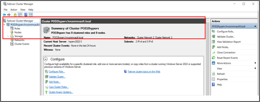
3. Add the SAN storage as Cluster Shared Volumes (CSVs) to enable simultaneous access by multiple Hyper-V hosts.
Configuring NIC Teaming on Hyper-V
To configure NIC Teaming on Hyper-V, complete the following steps:
1. From the Server Manager, navigate to NIC Teaming and set to Enabled.

2. Before teaming the NICs, ensure that the “Hyper-V Extensible Virtual Switch” property on the NICs is disabled.

3. Open the NIC Teaming wizard, assign a team name, and select the adapters to bind.
In this scenario, 4 x 25G NICs are selected to bind together as a team.
4. In Additional Properties, set Teaming mode to LACP and Load balancing mode to Hyper-V Port. Click Apply.

5. Create a virtual switch (vSwitch) with 25G NIC teamed adapter using Windows PowerShell with the command below:
Command Syntax-
New-VMSwitch -Name “SwitchName” -NetAdapterName “NICTeamName” -AllowNetlbfoTeams $true -AllowManagementOS $true
Example:

6. After successfully creating the NIC team and the vSwitch, assign an IPv4 address to the vSwitch in Network Connections and disable IPv6.

Creating and configuring the vSwitch from Hyper-V Manager
To create and configure the vSwitch from Hyper-V Manager, complete the following steps:
1. Create and configure the vSwitch from the Hyper-V Manager.
For more detailed steps, see: Create and configure a virtual switch with Hyper-V | Microsoft Learn.
2. After successful creation, the vSwitch appears in the Virtual Switch Manager, as shown in the following screenshot:

Creating and configuring VMs
To create and configure VMs, complete the following steps:
1. Create and configure a VM from the Hyper-V Manager.
For more detailed steps, see: Create a virtual machine in Hyper-V | Microsoft Learn.
2. After successful creation and configuration, the VM appears in the Hyper-V Manager, as shown in the following screenshot:

3. To start the installation, click Connect.
Summary
This blog shows how to implement the installation of the Hyper-V on a Windows 2022 server, the creation of a failover cluster using Failover Cluster Manager on a VSP E990 storage system over FC, the creation of NIC Teaming, the creation of vSwitches through PowerShell and Hyper-V Manager, and creation and configuration of VMs on Hyper-V.