Introduction
Universal Replicator (UR) operations involve two storage systems. One of the systems is located at the primary site, called main control unit, and the other system is located at the secondary site, called remote control unit.
The primary storage system controls the P-VOL and the following operations:
- Host I/Os to the P-VOL
- P-VOL data copy to the master journal
The secondary storage system controls the S-VOL and the following operations:
- Initial copy and update copy between the P-VOL and the restore journal
- Journal commands to the primary storage system
- Journal data copy from the master journal to the restore journal
- Restore journal data copy to the S-VOL
- Pair status management and configuration (for example, rejecting write I/Os to the S-VOLs)
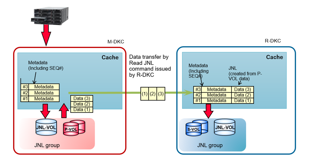
For Universal Replicator operations, journal volumes are required on the primary and secondary storage systems. Updates to the P-VOL are copied to the master journal volume in the primary storage system. Master journal data is copied to the restore journal volume on the secondary storage system. A Journal (JNL) group consists of one or more data volumes and the associated journal volume.
Journal enables you to manage data consistency between multiple P-VOLs and S-VOLs. A single journal volume can support up to 8,192 data volumes and the storage system can support up to 128 journal volumes for the VSP One Block 20 and VSP E series and up to 256 for the VSP 5000 series and VSP One Block High End storages. Despite these high limits, it is essential to design the appropriate number of journals and its capacity based on key parameters to prevent journal overflow and ensure smooth recovery in the event of a failure.
Use of Journal Volumes
- A Journal (JNL) group can contain up to two Journal volumes. The second journal volume is used as a reserve (spare) journal volume.
- The Journal volume (JNL-VOL) has a metadata area and a write data (JNL) area, and their capacity ratio is 1 (metadata) to 32 (write data).
- In the M-DKC, both the metadata area and the write data area are allocated when metadata is created for incoming write data. Both areas are released after it receives notification from the R-DKC that copying to the S-VOL has completed.
- The sufficient space of JNL volume in both M-DKC and R-DKC is important considering:
- If there is insufficient space in the M-DKC JNL-VOL:
- host write inflow may be slowed or stopped
- host write commands may be delayed
- SCSI reset may occur
Therefore, for “Inflow Control” of “Edit Journal Options”, it is recommended to set it to “No”, or set the I/O monitoring time to 1 minute
-
- If there is insufficient space in the R-DKC JNL-VOL, the next Read JNL commands from R-DKC will be delayed. This does not directly impact M-DKC host write processing, but the delay in Read JNL command issuance can eventually cause insufficient space in the M-DKC JNL-VOL.
- During Initial Copy, only the metadata area in the M-DKC journal volume is allocated but the write data (JNL data) area is not allocated. Data from the P-VOL (source) in M-DKC is transferred directly to the S-VOL (target) in R-DKC. This data transfer occurs without passing through the JNL-VOL.
Journal volumes should be sized appropriately to handle two critical business scenarios:
- Performance
- Disaster recovery
Journal Volumes Planning for Performance
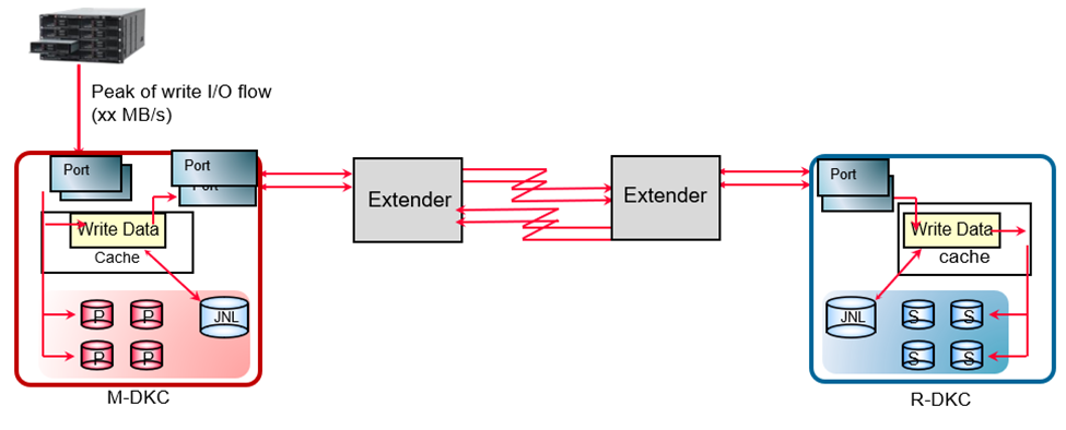
- An effective strategy involves optimizing the bandwidth (between the host and storage systems, and between the storage systems), along with determining the number and capacity of journal volumes.
- To ensure optimal system performance and prevent journal overflow under any business workload, the journal transfer speed must match or exceed the host I/O load. If the transfer speed is lower than the host I/O rate, journals may accumulate on the MCU, which can lead to overflow if the journal volume capacity is insufficient.
- To prevent performance deterioration of the host write I/O, a public line with sufficient bandwidth is required. The links between M-DKC and R-DKC must provide sufficient bandwidth to support the average throughput of the host write.
- If the inflow of host writes at peak period is predicted to exceed the remote path bandwidth, the JNL VOL storage capacity must be equal to or more than “(inflow amount - bandwidth) x time of inflow”.
- To prevent JNL data from being stored in the M-DKC’s JNL VOLs during peak periods then configure the links where the maximum inflow is smaller than the replication bandwidth.
- To ensure the bandwidth between the M-DKC and the R-DKC is larger than average throughput between the host and the M-DKC, the following factors must be considered:
- Type of the public line (DWDM/T3/ATM/IP), the number of public lines, and fiber channel/iSCSI links.
In an environment with a 256 Mbps or more line speed, a single UR Read JNL command can transfer up to 1 MB of data from the M-DKC to the R-DKC. As the number of JNL groups increases, more RDJNL commands can be issued simultaneously, allowing Initial Copy throughput to scale almost linearly with the number of JNL groups, up to the maximum limit supported by the storage array model.
The following example shows how Initial Copy and Resynchronization throughput increase as the number of JNL groups are increased on a VSP One Block High End 2N configuration using medium copy pace.
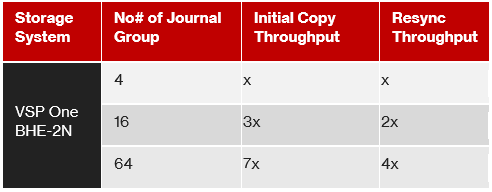
Note: Configuring too many JNL groups may negatively impact host response time. It is therefore recommended to use the preferred number of JNL groups for each storage system. For example, for a VSP One Block High End storage system, the recommended guideline is 4 JNL groups per MPU.
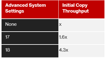
As an enhancement Hitachi has two settings that improve Initial Copy throughput in medium copy pace - Advanced system Settings #17 and #18.
By enabling Advanced system Settings #17 copy pace becomes one level faster (~150%) than medium copy pace. By enabling Advanced system Settings #18 copy pace becomes two levels faster (~400%) than medium copy pace. These two settings control how faster journal meta data is created which in turn enhances the copy pace. Here is an example with VSP One Block High End 2N storage system.
Additional Strategy
- When Initial Copy is performed with high copy pace, write IO is not recommended. If write IO is issued in high copy pace, host IO performance degrades substantially, pairs might also get suspended. A better solution is medium copy pace, where write I/O is accepted without much degradation in initial copy performance. Note that, for a standard configuration initial copy throughput in medium copy pace may be around 5 times less than high copy pace.
- Network bandwidth under impaired SAN/WAN conditions: Packet loss and latency in the inter-site network reduce effective replication throughput and increase in-flight data between sites. Loss introduces retransmissions that consume bandwidth and delay journal consistency, while latency increases the volume of uncommitted replication data still in transit. Therefore, when impairments are present, additional network bandwidth headroom is required from the provider to maintain the desired replication performance and consistency objectives.
- RAID group performance: Ensure that the RAID configuration supports the required throughput.
Journal Volumes Planning for Disaster Recovery
In a UR solution, the journals remain relatively empty when the data path keeps up with the inflow rate of the updated data to the secondary site. However, there can be times where the network between the sites is down or becomes unstable. It is important to size the journals properly to meet your Recovery Point Objective (RPO). RPO is the maximum time that can pass after a failure, or a disaster occurs before the data loss is greater than the operation can tolerate.
To correctly size the journals, you must determine the following:
- The amount of changed data that the applications generate.
- The maximum amount of time that the journals can accumulate updated data. This information depends on the desired recovery point objective.
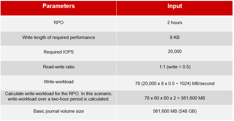
Journal volume capacity is determined considering worst-case scenarios, such as link failure between two data centers. The following table is an example of calculating the required journal volume capacity using a 50% 8KB write-workload and RPO.
A more efficient system design would be dividing the required journal capacity into multiple journal groups and associating them with a fixed number of P-VOLs and MPUs. The above calculation applies to both FC and iSCSI configuration. Choose an appropriate number of Fibre Channel or iSCSI ports based on their IOPS thresholds and the production system’s required IOPS.
Note: This is not an exhaustive list of sizing strategies, and your final design may combine multiple approaches to meet specific business and operational requirements. For environments with critical business SLAs, a comprehensive remote copy design and capacity planning exercise is required. This should be performed in collaboration with pre-sales Technical Engineers and Professional Services to validate topology, bandwidth, latency tolerance, journal sizing, and failure scenarios, ensuring the Universal Replicator solution meets availability and recovery objectives.
Recovery from Journal Failure
If data in the journal volume exceeds the threshold (80 %), pair status changes (e.g., PAIR to PFUL and PSUS to PFUS) and eventually pair suspension due to error (PSUE) occurs. When pairs are suspended, we can increase the journal volume size and then, perform resync operation to establish the pair again. When the pair is resynchronized, the primary and secondary storage systems perform the following operations:
- The secondary storage system sends the S-VOL bitmap to the primary storage system
- The primary storage system merges the P-VOL and S-VOL bitmaps to synchronize the tracks.
These actions ensure that all cylinders/tracks containing journal data discarded on the secondary storage system are resynchronized.
Summary
Universal Replicator uses journal volumes to maintain data consistency between primary and secondary storage systems. Proper sizing of journal capacity and transfer bandwidth is critical to prevent journal overflow and meet Recovery Point Objectives (RPO) and desire performance. Review the performance test results from Solution Engineering & Architecture (SEA). For more details, contact your Hitachi Vantara representative.
#DataProtection
#StorageManagement