Introduction
Hitachi Content Platform (HCP) is a distributed object storage platform designed for scalable management of fixed-content data. It stores data as objects with associated metadata and provides access through URLs or standard file system interfaces. HCP organizes data into tenant-managed namespaces for efficient storage, protection, and retrieval across enterprise environments.
Overview
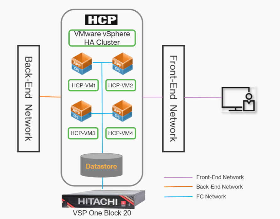
The test environment consists of a Hitachi Content Platform deployment running on a VMware vSphere HA cluster to provide high availability and service continuity during ESXi host failures. The HCP cluster includes four VM nodes-HCP-VM1, HCP-VM2, HCP-VM3, and HCP-VM4-delivering scalable and redundant object storage services. All VM disks are hosted on a shared datastore backed by VSP One Block 20 storage. The front-end network is used for client access and management traffic, while the back-end network handles internode communication, metadata synchronization, and replication traffic between HCP VM nodes.
A 4-node configuration is intentionally selected as the baseline for this environment to provide a balanced and resilient architecture. This setup enables built-in redundancy, ensuring that workloads and data are distributed across multiple nodes, thereby eliminating single points of failure. From a cluster design perspective, four nodes allow the system to maintain a reliable quorum, which is essential for consistent cluster decision-making and preventing split-brain scenarios. Even in the event of a node failure, the remaining nodes can continue to maintain quorum and sustain normal operations.
Test environment
Key Components
1. HCP-VMs:
A HCP VM node requires a minimum of eight virtual CPUs and 32 GB of allocated RAM. These processing requirements ensure that system performance remains stable during multiple client logins and that critical operations, such as encryption, scheduled services, and routine database maintenance, continue to run without interruption.
For deployments using the HCP VM small-instance configuration, each HCP VM node must be provisioned with at least four virtual CPUs and 16 GB of allocated RAM.
As a best practice, the HCP-VM nodes should be deployed on different ESXI hosts to minimize the risk of service disruption and prevent outages caused by a single host failure.
2. Storage:
The HCP VM storage infrastructure is designed for high availability and fault tolerance. As a best practice, the physical servers hosting the ESXi instances should be connected to shared SAN storage configured with RAID 6 to ensure data protection and resiliency.
3. VMware datastores:
Select an appropriate datastore to store the VMDK files for the HCP node virtual machines.
Provision all VMDKs using the thick eager-zeroed format to prevent storage overprovisioning and ensure consistent performance for HCP VMs.
Configure the ESXi hosts and underlying storage environment in alignment with VMware best practices, even when using a standard (non-vSAN) datastore.
4. HCP VM Network Connectivity:
HCP VM network connectivity is provided to the guest operating system through VMware VMXNET3 virtual network interfaces (vNICs) connected to vSwitches or distributed switches.
For proper traffic separation, the back-end network should be configured on a vSwitch backed by one or more dedicated physical NICs (vmnics), while the front-end network should use a different vSwitch backed by separate vmnic uplinks. This design ensures effective network isolation, redundancy, and consistent performance.
Front-End Network- The HCP front-end network supports client access and management operations. As a best practice, the ESXi host should be configured with a single vSwitch or port group backed by two physical NICs (vmnics). Using dual vmnics provides redundancy and helps maintain consistent network performance.
Back-End Network- The HCP private back-end network is dedicated to internode communication and data transfer. On the ESXi host, the back-end network should be configured on a vSwitch or port group backed by two physical NICs (vmnics) on the server, ensuring reliable and efficient back-end network connectivity.
5. HCP Software:
HCP VM systems run the same HCP operating system and software stack as HCP systems that use internal storage or SAN-attached storage, ensuring consistent functionality and behavior across all deployment models.
Prerequisites
1. Virtualization Platform
- VMware vSphere environment with HA enabled
- One or more ESXi hosts configured as part of a vSphere HA cluster
- ESXi hosts must support:
- VMXNET3 virtual network adapters
- Shared datastore access
- Required CPU and memory resources for HCP VMs
2. Compute Resources
- Adequate CPU and memory capacity on ESXi hosts to support multiple HCP VM nodes:
- Sufficient vCPUs and RAM allocated per HCP VM node
- Enough headroom to allow VMware HA failover without resource contention
3. Storage Prerequisites
- Shared datastore (Datastore1) presented to all ESXi hosts in the HA cluster
- Storage must provide:
- High availability and fault tolerance
- Consistent performance for HCP workloads
- Datastore accessible concurrently by all HCP VM nodes
4. HCP VMs Configuration
To deploy an HCP VM system, begin by connecting to the vCenter Server where the vSphere HA cluster for HCP has been configured. From the vSphere navigation pane, right-click on the target ESXi host and start the New Virtual Machine wizard.
Choose Create a new virtual machine, then provide a meaningful name for the VM and select the appropriate datacenter. Next, select the ESXi host and the shared datastore intended for the HCP deployment. When prompted for compatibility, choose a suitable VM hardware version. Set the Guest OS family to Linux and the Guest OS version to Red Hat Enterprise Linux 6 (64-bit).
Configure the virtual hardware with the required resources:
- Assign 8 vCPUs, configured as 4 cores per socket.
- Allocate 32 GB or 64 GB of memory, depending on the deployment requirement.
- Create the primary operating system disk with a minimum size of 32 GB, using thick-provisioned, eager-zeroed disk provisioning.
For additional storage, add one or more new hard disks:
- Allocate at least 50 GB for a dedicated database volume.
- Ensure all additional disks are also provisioned as thick eager-zeroed to guarantee consistent performance.
Once all settings are reviewed
- Configure the first network adapter by assigning it to the Front-End Network, enabling Connect at Power On, and setting the adapter type to VMXNET3.
- Configure the second network adapter by assigning it to the Back-End Network, enabling Connect at Power On, and setting the adapter type to VMXNET3.
- From the New CD/DVD Drive options, select Datastore ISO File.
- Click Browse next to CD/DVD Media, choose the ISO file that was previously unpacked and uploaded, and then click OK.
- Enable Connect at Power On for the CD/DVD drive.
- Click Next, review all configuration settings, and then click Finish to complete the setup.
5. Network Prerequisites
Front-End Network
- Dedicated front-end network for:
- Client access
- Management and administrative traffic
- Proper network connectivity from external client systems to HCP VMs
- vSwitch or distributed switch configured for front-end traffic
Back-End Network
- Private back-end network dedicated to:
- Internode communication
- Metadata exchange
- Data replication between HCP VM nodes
- Network isolated from front-end traffic to ensure performance and reliability
6. Network Adapter Configuration
- VMware VMXNET3 vNICs configured for all HCP VMs
- Separate virtual networks for:
- Front-end traffic
- Back-end traffic
- Proper vSwitch/dvSwitch configuration on ESXi hosts
7. High Availability and Resiliency
- VMware vSphere HA is properly configured and tested
- Shared storage and networking must support automatic VM restart on host failure
- No single points of failure in compute, storage, or networking layers
8. Management and Access
- Administrative access to:
- vCenter Server
- ESXi hosts
- Storage management interfaces (VSP One Block 20)
- Network connectivity for HCP management interfaces
Hardware
Table 1 provides the hardware used for testing.
|
Item
|
Description
|
Quantity
|
|
1. Physical Server
|
HPE DL360 G10
2x Intel Xeon Silver 4110 8-core 2.1GHz
128 GB memory
2x 25G NICs
|
1
|
|
2. Physical Storage
|
Hitachi VSP One Block 24
|
1
|
|
3. Ethernet Switch
|
Cisco Nexus 9000 Series switch for 25G network connectivity.
|
1
|
|
4. FC Switch
|
Brocade G720 for 32G/64G SAN connectivity.
|
1
|
Software
Table 2 provides the software used for testing.
|
Item
|
Version
|
Quantity
|
|
1. Production hosts
|
ESXi 8.0.3
|
1
|
|
2. HCP VMs
|
HCP Operating System 10.0.1
|
1
|
|
3. DNS Server
|
Windows Server 2022
|
1
|
|
4. VSP One Block 24
|
Microcode: SVOS 10.4.1
|
1
|
Installation of the Appliance Operating System
After deploying the ISO file, complete the following steps for each HCP VM node in the vSphere cluster.
Before You Begin
Obtain the required network details from your network administrator, including the front-end IP addresses, subnet mask, default gateway, and back-end IP addresses. All back-end IP addresses must reside on the same subnet. For simpler installation and easier ongoing support, it is recommended that the last octet of the front-end and back-end IP addresses be assigned sequentially.
Procedure
1. Power on the first HCP VM node.
2. Launch the vSphere Client.
3. In the left navigation pane, right-click the lowest-numbered HCP VM node and select Open Console.
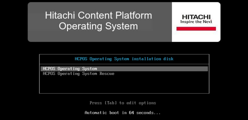
The installation program will then prompt you to choose the installation mode.
4. Enter c to remove any existing storage volumes.
When prompted to confirm the action, type y.
5. If you selected IPv4 or dual‑stack mode, provide the node’s IPv4 address along with the subnet mask and default gateway for the front‑end network, and the IPv4 address with subnet mask for the back‑end network.
6. Type y to confirm.
7. The operating system installation has been completed successfully. Repeat the same installation steps for the remaining three virtual machines.
Configuration of HCP Software
The HCP installation is initiated from the node that has the highest value in the last octet of its back-end IP address.
Launch the vSphere Client.
1. From the left navigation pane, choose the HCP VM node that has the highest value in the last octet of its back-end IP address.
2. Right-click the selected virtual machine and select Open Console.
3. Sign in to the HCP VM node console using the default credentials.
Username: install
Password: Chang3Me!
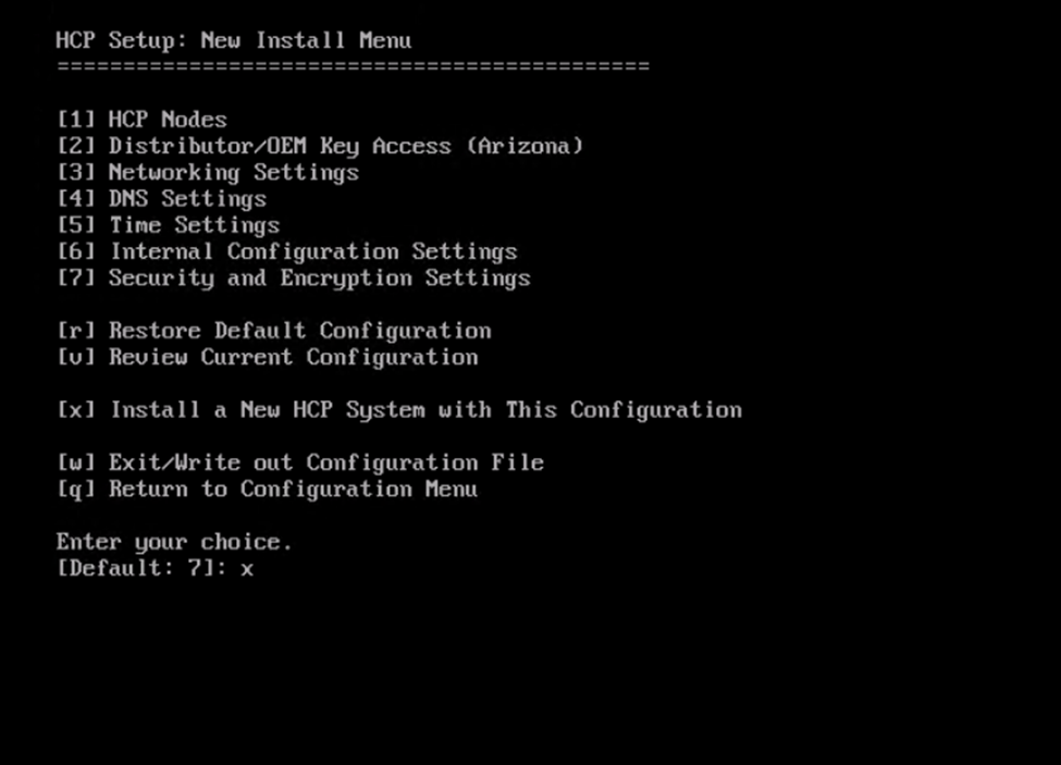
4. Enter 3 to proceed with installing the HCP system.
Important: Explanation of Critical Parameters
During the configuration process, you will encounter several system-defined parameters that are essential for proper cluster initialization and operation:
- Distributor key
- Replication-on-time
- Internal storage selection
Note: These parameters are preconfigured for optimal deployment and must not be modified unless explicitly instructed by Hitachi Support. Incorrect configuration may lead to issues with cluster formation, replication behavior, or licensing.
5. Press 1 to configure HCP Nodes.
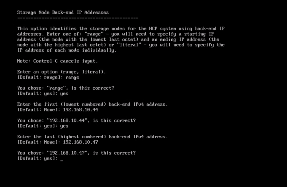
6. Enter 1 to specify the storage node back-end IP address.
7. Enter the IP address range by specifying the lowest and highest values for the back-end network IP addresses.
Type yes to confirm and proceed.
Type yes to confirm.
Then press b to return to the previous menu.
8. Enter 2, and specify the distributor key details.
Note: Do not modify the Arizona key if the system is supplied by Hitachi Vantara; the default setting must be used.
Type y or yes to confirm the change.
9. Press 3 to enter and configure the network settings.
· Within the network settings, specify the gateway address.
Important: Multicast in HCP:
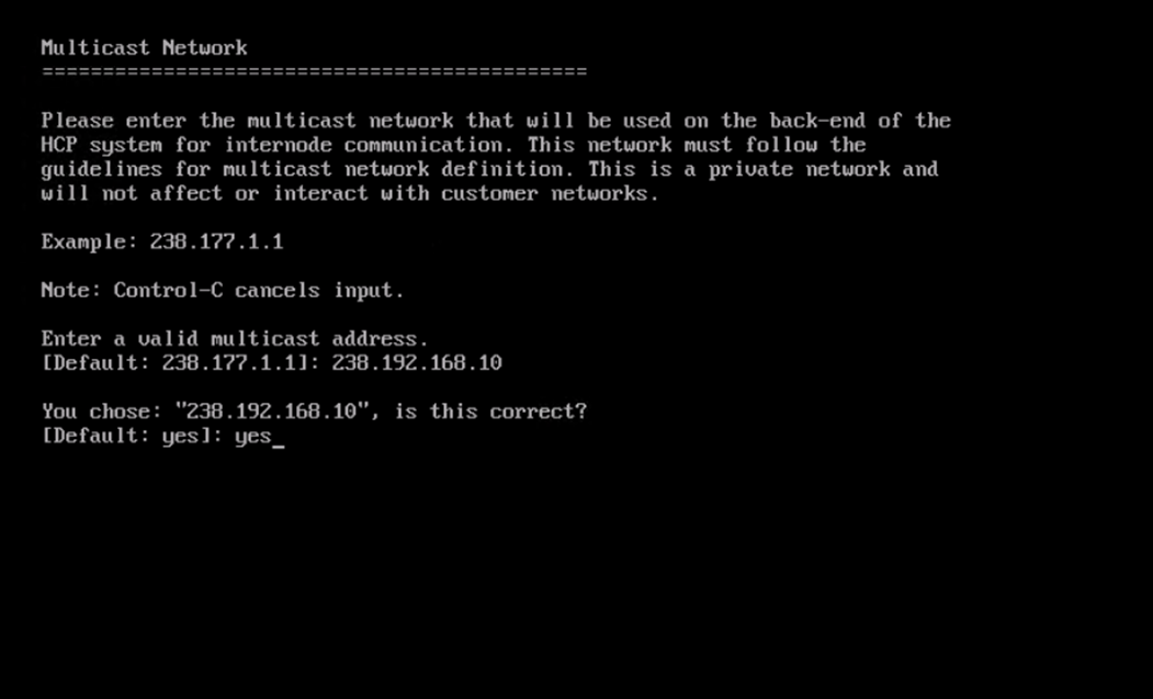
Multicast is the inter-node communication mechanism used on the back-end (BE) network. HCP nodes use a multicast IP address to broadcast messages to all other nodes in the cluster — things like cluster membership, health checks, metadata synchronization, and service coordination. It's essentially how nodes "discover" and "talk to" each other internally.
What Value to Provide
The multicast address follows a simple rule:
238 + first 3 octets of the back-end IP address
Examples:
|
Back-End IP Range
|
Multicast Address
|
|
172.101.40.x
|
238.172.101.40
|
|
172.150.235.x
|
238.172.150.235
|
|
172.59.42.x
|
238.172.59.42
|
The default proposed by the HCP installer is 238.177.1.1 — which is what the screenshot shows. This default is fine if the BE IPs start with 177.1.1.x; it should be adjusted to match the actual BE subnet.
Provide the multicast network details and click yes to confirm.
Enter b to return to the New Install Menu
10. Press 4 to configure DNS Settings.
- Enter 2 to specify the domain name for the HCP system. After the domain name is configured,
- Select option 3 to define the DNS settings, and then enter the IP address of the DNS server to enable proper name resolution and network communication.
- Then press b to go back to the previous menu.
11. Choose 5 to modify the time settings.
Press 1 to enter the time server (NTP) IP address, and then press 3 to select and configure the appropriate time zone for the system.
12. Press 6 to configure internal configuration settings.
Under internal configuration settings
- Press 1 to configure the storage type and set it to Internal storage. Next,
- Press 2 to enter the Serial number of the HCP system, which uniquely identifies the deployment. Then,
- Select option 3 to configure the Replication-on-time settings, ensuring that the system time is properly synchronized for replication and internal processes.
- Finally, press 4 to configure the Reinstallation settings, leaving the DNS failover option set to the default value of “No”, unless a specific DNS failover requirement exists.
Press b to go back to the previous menu.
13. From the New Install menu, enter x to continue.
The wizard then displays a configuration summary.
- Enter yes to proceed.
- Press Enter to confirm your selection.
- Review the settings carefully and type yes to confirm and continue.
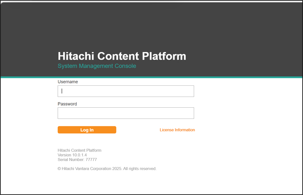
14. Once the installation is complete, to access the System Management Console, open a web browser on a client system and enter one of the following URLs:
- If DNS is configured for the HCP system: https://admin.hcp-domain-name:8000
- If DNS is not configured for the HCP system: https://node-ip-address:8000
In this case, node-ip-address refers to the front-end IP address of any storage node in the HCP system.
Username: security
Password: Chang3Me!
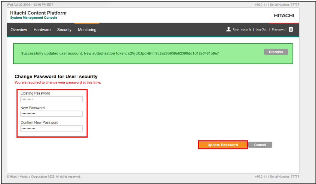
On the Change Password screen, provide the following details:
- In the Existing Password field, enter the default password.
- In the New Password field, specify a new password.
- Click on Update Password.
Summary
This document provides a comprehensive overview of deploying and configuring a Hitachi Content Platform (HCP) virtual appliance in a VMware vSphere® environment. It covers the complete lifecycle of an HCP setup, starting from appliance installation through configuration.
The guide is intended for technical personnel responsible for deploying HCP VM systems at customer sites and assumes prior experience with virtualization, networking, and VMware technologies, along with a basic understanding of HCP concepts.
For more information, please refer to the reference documentation https://docs.hitachivantara.com/v/u/en-us/mk-94hcp010/latest.
#ContentPlatform