This blog describes how Windows Server Failover Clustering (WSFC) on Windows Server 2025 can use Storage Spaces Direct (S2D) volumes and external SAN volumes on Hitachi VSP One Block side‑by‑side within the same cluster. The intent is to reflect a joint Hitachi Vantara + Microsoft approach that preserves customer choice: Microsoft provides the virtualization and clustering platform primitives, while Hitachi Vantara provides enterprise SAN storage and associated operational patterns for performance, resiliency, and data services.
Key idea: This mixed topology is a supported, flexible architectural pattern (described as “Hyperconverged with SAN storage” / mixed topology by Microsoft) where S2D and SAN remain logically separate, but are both consumed by clustered roles such as Hyper‑V VMs.
This blog reflects validation performed by Hitachi Vantara engineering using a production‑representative lab environment. Special thanks to Hossein Heidarian (https://www.linkedin.com/in/hosseinheidarian/) and Imran Shaik (https://www.linkedin.com/in/imran-shaik-5a39b0111/) for their significant contributions to SAN configuration, Windows Server Failover Clustering (WSFC) validation, and failure‑mode testing.
1. Executive summary
Windows Server 2025 WSFC/Hyper‑V supports multiple validated storage architectures, including mixed and hybrid patterns that combine S2D CSVs and SAN‑backed CSVs within the same cluster. This enables investment protection (reuse existing & expand SAN) and architectural flexibility across workload profiles, without forcing architectural lock-in and disruptive migrations.
From a solution perspective:
- Microsoft delivers robust virtualization and clustering primitives (Hyper‑V, WSFC, CSV/CSVFS) plus an integrated software‑defined storage option (S2D).
- Hitachi Vantara delivers enterprise‑class primary storage (SAN) with mature operational runbooks and data services (for example, snapshot/replication/cyber‑resilience patterns).
Together, customers can align storage selection to workload requirements and operational preference, and can move VM storage between tiers using Hyper‑V storage migration.
Simply put, our solution offers reliable architectural versatility to accommodate a wide range of changing workload needs.
Completed validation highlights (in our lab environment):
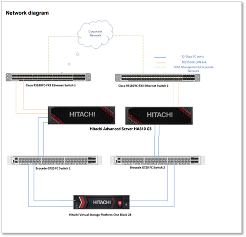
Lab setup: Two Hitachi Advanced Server HA 810 G3 nodes connect to dual Top‑of‑Rack switches for data networking and a dedicated management switch for administration. Each node has two FC HBAs connected to Brocade G720 SAN switches, providing redundant paths to Hitachi Block 28 Storage for shared storage access.
- SAN LUNs were presented as clustered disks and added as Cluster Shared Volumes (CSVs) with MPIO configured and stable operation.
- Coexistence was validated: VM templates/images can reside on an S2D CSV while VM OS/data lives on a SAN CSV, with normal VM lifecycle operations.
- Mobility was validated: two‑way VM storage movement between SAN CSV and S2D CSV using Hyper‑V Storage Migration (example shown with Move‑VMStorage).
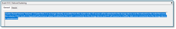
- Resiliency was validated: VM workload remained available during FC path failures; with all paths lost on one node, CSVFS entered Block Redirected Mode and returned to Direct Mode after paths were restored (Event ID 5121 captured).
Note: At the time this report was written, the iSCSI configuration had not been validated. Nevertheless, it is expected to be simpler than the Fibre Channel setup because it requires fewer components.
2. What “coexistence” means in WSFC 2025
In this document, coexistence means:
- S2D‑backed volumes (commonly ReFS CSVs) provide Microsoft‑integrated, software‑defined storage built from local disks in the cluster nodes.
- External SAN LUNs (commonly NTFS CSVs) are presented to all cluster nodes over FC/iSCSI and added as clustered disks/CSVs.
- Both storage types are used concurrently by clustered roles (for example Hyper‑V VMs), while remaining logically separate—SAN LUNs are not added to the S2D pool.
Microsoft documentation explicitly calls out mixed topologies such as “Hyperconverged with SAN storage” where S2D and SAN volumes exist in the same WSFC cluster.
Operationally, coexistence was demonstrated by placing VM image assets on an S2D‑backed CSV while placing VM OS/data on a SAN‑backed CSV—with no loss of VM lifecycle functionality in the validation environment.
3. Completed validations: what we already proved
3.1 Foundational storage attach & correctness (SAN → CSV)
This is the prerequisite setup. All subsequent scenarios depend on correct SAN presentation and cluster validation.
Validated sequence (high level):
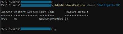
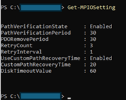
1. Install FC HBA + certified drivers; enable/configure MPIO (MSDSM; Round‑Robin observed effective).
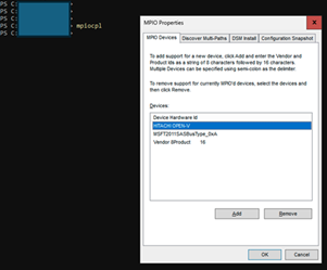
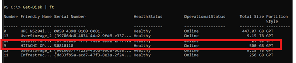
2. Reboot nodes; add MSDSM auto‑claim policy for Hitachi (example: mpclaim -r -i -d "HITACHI OPEN-V").
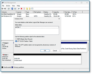
3. Create/unmask SAN volumes to all hosts; rescan, initialize GPT/NTFS.
4. Run Test‑Cluster before production use; add SAN volumes as Cluster Disks → CSVs.
Tasks (completed):
· Install FC HBA and certified drivers on each node
· Enable and configure MPIO (per storage vendor best practices)
o Observation: MSDSM with Round‑Robin was effective for the Hitachi SAN in this environment.
· Reboot nodes to apply MPIO settings
· Configure MSDSM auto‑claim policy for Hitachi OPEN‑V (mpclaim …)
· Zone/register FC WWNs for each host with the SAN fabric
· Create and unmask SAN volumes to all cluster hosts
· Rescan hosts to detect new volumes
· Initialize and format SAN volumes as GPT/NTFS
· Validate cluster storage with Test‑Cluster
· Add SAN volumes as Cluster Shared Volumes (CSVs)
3.2 Blended VM operations on SAN-backed CSVs
While WSFC operates stably and reliably with SAN, we have verified that VM lifecycle operations—such as creation, stop-start, disk attachment, and expansion—work correctly on SAN CSVs following SAN attachment, using procedures similar to routine operations. This lays the groundwork for later verifying two-way live storage migration.
Validated behaviors:
- VM template/image assets can reside on an S2D CSV while VM OS/data is created on the SAN CSV (practical coexistence).
- VM stop/start operations with disks on SAN showed no loss of functionality (in this environment).
- Adding a data disk to a VM requires initializing the disk inside the guest OS after attach (observed behavior).
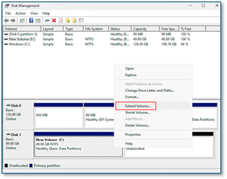
- Disk expansion requires extending the volume in the guest after the platform‑side expansion (observed behavior).
3.3 Two-way live storage movement between SAN and S2D
We demonstrated moving VM storage between SAN CSV and S2D CSV using Hyper‑V Storage Migration (e.g., Move‑VMStorage) in both directions, without observed service interruption in the validation environment.
Example (PowerShell):
Confirm current VM storage path:
· Get-VM -Name vm1 | Select VMName, State, Path
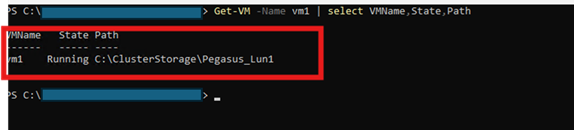
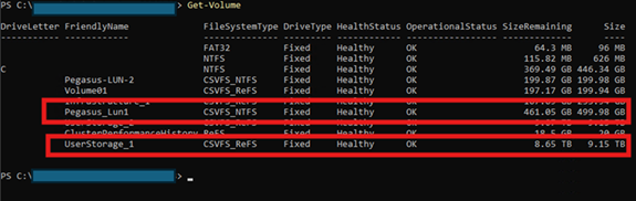
· Observation: output showed the VM OS located on the SAN volume (example: Pegasus‑LUN‑1).
Migrate VM storage from SAN CSV to S2D CSV:
· Move-VMStorage -Name vm1 -DestinationStoragePath C:\ClusterStorage\UserStorage_1\ -Verbose
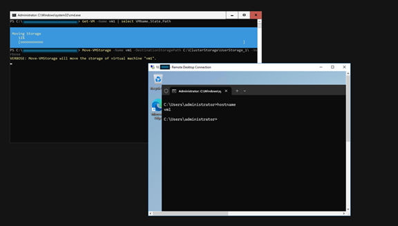
· Observation: VM storage moved from the SAN path to the S2D path without interruption in the validation environment.
Re‑check VM storage path:
· Get-VM -Name vm1 | Select VMName, State, Path
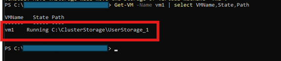
· Observation: output showed the VM OS moved to the S2D CSV (UserStorage_1).
Migration of VM storage from S2D CSV to SAN CSV was successful and proceeded as anticipated.
If you’re looking for more technical information, take a look at this excellent article by Microsoft WSFC PM: Announcing Support for S2D and SAN Coexistence | Microsoft Community Hub
3.4 Resiliency: storage path disruption and CSV behavior
To further demonstrate the resilience of WSFC and SAN to audiences unfamiliar with these systems, we conducted additional tests under various scenarios. Fibre Channel (FC) path failures were introduced, yet workloads continued to operate uninterrupted. In cases of complete path loss on a node, CSVFS transitioned to redirected I/O mode to maintain availability and subsequently reverted to Direct Mode once paths were restored. This outcome is consistent with established CSV behavior guidelines and state concepts.
3.4.1 Node failure (tested)
· Hard power off one node via KVM (“cold boot” scenario).
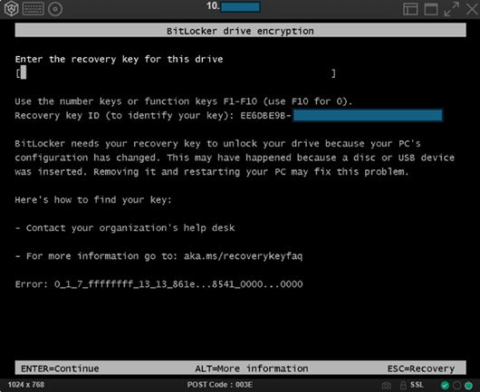
o Observation: cold boot may activate BitLocker protection (previously observed in this environment).
· Verify VMs restart on available node and storage remains accessible.
o Observation: VM disruption occurred immediately after cold boot; VM became operational again on the remaining node in ~90 seconds; no data loss observed.
3.4.2 Single‑path failure (tested)
· Disabled one FC port and verified the VM workload remained uninterrupted (no resource failover required).
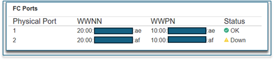
o Observation: path failure introduced at the switch; VM I/O remained uninterrupted the entire time.
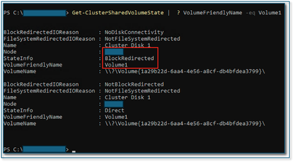
3.4.3 All‑path failure on a node (tested)
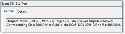
· Disabled all FC ports on one node
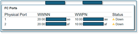
· VM remained running and I/O continued through CSVFS proxy stack with Block Redirected Mode triggered; after restoring paths, system returned to Direct Mode within ~30–60 seconds.
o Observation: VM I/O remained uninterrupted the entire time. However, for VMs demanding higher I/O performance, failover to another cluster node may occur.
3.4.4 Alerting and logs to capture (tested)
Operator‑focused observability captured:
· System log: Event ID 5121 as a primary signal for redirected I/O due to loss of direct volume accessibility.
· Additional sources: mpio; StorPort Operational; FailoverClustering‑Csvfs Operational; FailoverClustering Operational.
4. Conclusion - Key concepts WSFC + SAN
From a business standpoint, WSFC mixed‑storage coexistence is primarily about investment protection and phased modernization: customers can keep their trusted SAN operational model for mission‑critical workloads while selectively adopting S2D where it provides platform‑integrated benefits—without forcing disruptive “big‑bang” storage migrations or architectural lock‑in.
This aligns with Microsoft’s published support for mixed topologies (including “Hyperconverged with SAN storage”) and our solution messaging that the data plane (SAN) can remain a constant while customers choose the Microsoft control plane and operating model that best fits their organization.
4.1 CSV and CSVFS: why they are the coexistence “glue”
A Cluster Shared Volume (CSV) enables multiple nodes to have concurrent read‑write access to the same volume, with CSV providing a clustered file system abstraction on top of NTFS or ReFS. Under certain conditions, I/O can become redirected through another node to preserve availability, which can reduce performance relative to Direct Mode. Operators should distinguish between redirected modes expected during specific operations and those indicating storage/fabric issues.
4.2 Placement strategy: choosing SAN vs. S2D (workload‑ and operations‑driven)
In a mixed‑storage WSFC cluster, customers can align storage choices with workload requirements and operational preferences:
- SAN CSVs: fit customers who standardize on enterprise primary storage for consistent performance, mature operational runbooks, and advanced data services, while keeping compute and storage lifecycles decoupled. (Common motivation described by Microsoft as leveraging SAN features such as snapshots/backups alongside S2D volumes.)
- S2D CSVs: fit customers who prefer a Microsoft‑integrated, software‑defined storage option that scales with cluster nodes and is managed as part of the Windows platform.
A common pattern is to use both where appropriate and leverage Hyper‑V storage mobility to move workloads between S2D and SAN as needs evolve.
#HitachiIntegratedSystems